How to Draw Squares Accurately in Perspective using Projection
03 April 2021
This post was originally published on Wordpress by Tarren Stroud (pixelglade's other alias) on 03 April 2021. It has been reposted for archival purposes. All images have been converted to clickable thumbnails at 100px height. Click to load the fullsize image.
In this tutorial I will share some perspective drawing exercises that can help you develop and improve your perspective skills in order to eventually draw room interiors, backgrounds, or architecture. If you struggle to visualize objects in your head and place them in a scene in a way that looks accurate or realistic, doing these exercises can help you.
Perspective projection is a method used by engineers, designers, and architects in order to project 2D shapes precisely from a blueprint into a rendered 3D environment. With solid drafting techniques you can achieve greater depth in your illustrations and paintings.
In this blog post, following an introduction, you will learn the necessary skills in order to:
- Put a square in one point perspective
- Give height to an object in perspective
- Draw a wall with width and depth
- Draw a diamond in one point perspective (or rotated square)
- Project a square at any angle into perspective
You do not need to go to an art class to learn these skills, as the information is available for free online. You can use a pencil, pen, and sketchbook for these exercises, or you can set up your digital painting workspace to do it. Wherever the instructions say to use a compass, if you do not have one you can just use a ruler. A compass is quicker to create measurements and marks with but it is not a requirement at this stage.
The content of this post is translated from French to English by myself with images and text sourced from the public domain book Elements de Perspective by Armand Cassagne (originally published 1874) available on the Internet Archive. I did this because I felt it provided clear illustrations and instructions and wanted to draw attention to this useful resource that most might not be able to fully access without a translation.
What is one-point perspective?
The goal of painting is to represent as faithfully as possible on a surface plane, objects placed before our eyes. We cannot arrive at this representation without the aid of perspective which by exact rules, give to the drawing the illusion of depth, and objects appear real with differences conveyed by these forms by their position and distance.
There are four different methods for representing an object:
- The Geometric Plan: which is traced exactly by all the lines of an object beneath the terrain. This plan always shows exact and proportional dimensions.
- Elevation: The cross section which defines the object’s height.
- The Perspective Plan: The geometric plan put in perspective.
- The Elevated Perspective: The representation of the object with the appearance of relief or thickness.
The object is perceived with the help of visual rays which come from the center of the eye and go toward each point of the object.
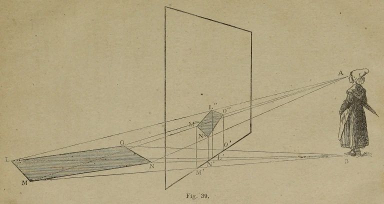
A screen is placed vertically between the spectator AB (Fig. 39) and the object to represent, the square LMNO. We see the image that the square produces on the screen is at the intersection between the visual rays going to the eye of the spectator.
The lines LB-MB-NB-OB, go to the feet, B, of the spectator along the angles of the square, and the verticals M’M”-L’L”-N’N”-O’O”, elevated at the intersection of these lines at the base of the screen represent the distances OO’-NN’-MM’-LL’ which help make the square on the screen.
The drawing area contains the ensemble of objects, contained within the gaze of the spectator. This surface is where we represent our drawing. The drawing area is in theory placed between the spectator and the object to be represented. The drawing area is divided into two parts: 1) the superior part represents the sky or a surface supposedly horizontal (the convex nature of the earth is not perceivable to the eye) and 2) the inferior part, the ground. The line which separates the drawing area into two areas is called the line of the horizon, and this line is not visible unless at the edge of the ocean.
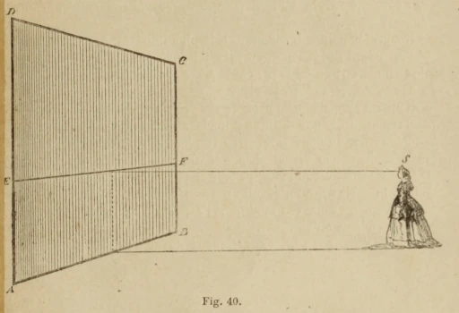
Spectator S (Fig. 40) represents their horizon (EF) on the image plane ABCD, at a distance AE from the base equal to the distance of the spectator’s feet to their eyes.
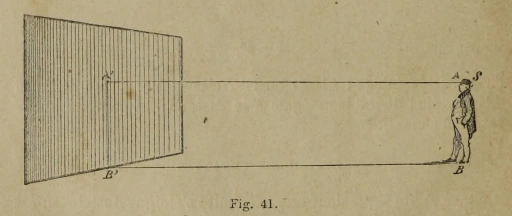
The spectator S (Fig. 41) is placed in such a way that their point of view (POV) is right in the center of the image plane (A”). All the parallel lines emanate from this point in perspective.
In perspective lines recede towards the horizon at a given point, the principal point or primary vanishing point. All these lines receding to the same point are parallel (although they might not appear so in perspective due to the distortion from our eye).
The point of distance is another point on the horizon, which helps define the scale of the object and make all shapes appear regular. The distance of the point of distance to the horizon is the same distance of the main vanishing point to the drawing area. When drawing a square, the point of distance defines the oblique diagonals at 45 degrees.
An important thing to remember is that the point of distance is not a second vanishing point even though it may look like it. If we were to have a second vanishing point to define an object that would be two point perspective not one point perspective. It gets intuitively easier to understand the point of distance with practice, so let’s move on to the exercises.
How to draw a square in perspective with a central vanishing point
The following square recedes in perspective to the vanishing point from the point of view of the spectator and underneath the horizon line.
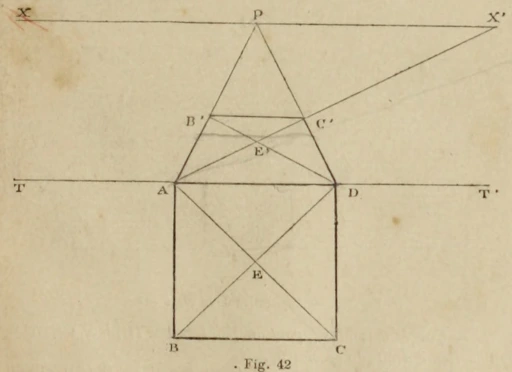
The given square in the practice of perspective is the figure most simple, and forms in some respects the base of this study, as we will see. The square is used to determine the other shapes, so we will begin by figuring out its principal positions relative to the spectator.
Operation: Given the geometric plan of the square (fig 42) underneath the line of the plan (1), in ABCD, and its center is determined by E by the intersection of diagonals, produce to the principal point P the receding lines AP-DP, and the point of distance X’ the diagonal vanishing line DC’ equal to the geometric side DC. Produce the horizonal line C’B’, which finishes the square AB’C’D, equal to the geometry of ABCD, and the diagonal B’D, which indicates the center of perspective of E’, correspondent to the center E.
(1) The line of the plan is at the base of the working area, which is up against the ground.
How to project a square to the side in perspective
In the following exercise, a horizontal square recedes to a point of view and is placed underneath the horizon to the right of the spectator.
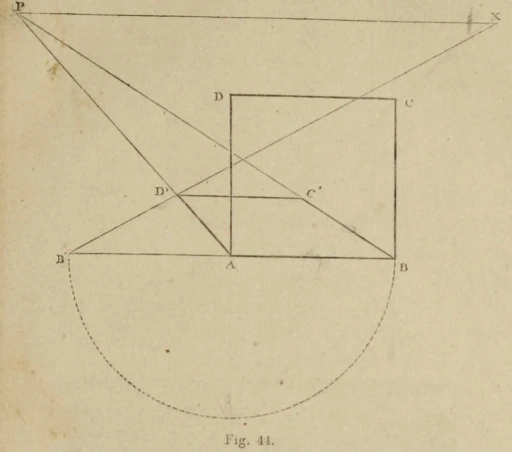
This parallel projection exercise is in pages 024-025 of the Internet Archive file and pages 18-19 in the volume.Fig. 44 depicts a base square and front-facing square in perspective with the same dimensions.
Operation: The point of view is given in P (Fig. 44), and the distance determined by X, construct the geometric square ABCD and prolong the horizontal line AB to AB’; plus, construct the receding lines AP-BP and the receding diagonal B’X, which determines on AP the depth of AD’ in perspective equal to the geometric square AD. Construct the horizontal line D’C’, which terminates the receding square ABC’D’, the appearance in perspective of the geometric square ABCD.
How to draw a wall or fence of a given height, width, and length
The following exercise could be applied to draw the walls of a room or a fence outside.
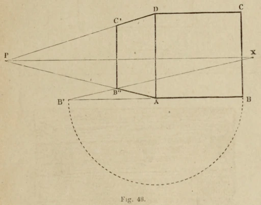
A vertical square recedes to the point of view and is placed on the line of horizon at the right of the spectator.
Operation: Given (Fig. 48) the geometric square ABCD, the horizon line PX, the point of view P, and the point of distance X, construct the receding lines AP-DP, and make the horizontal line AB’ equal to AB. Create the receding diagonal B’X which determines the depth AB’, and elevate the vertical B”C’ which terminates the receding vertical square ADC’B”, the appearance in perspective of the geometric square ABCD.
How to draw a diamond or rotated square in parallel perspective
This next exercise might be a bit trickier, but if you have done the previous exercises, you should be able to figure it out with some patience.
We recognize that the square is viewed from an angle while one of its diagonals is parallel to the horizon; in this case, the other diagonal is receding at a right angle from the point of view, and its sides run towards the points of distance.
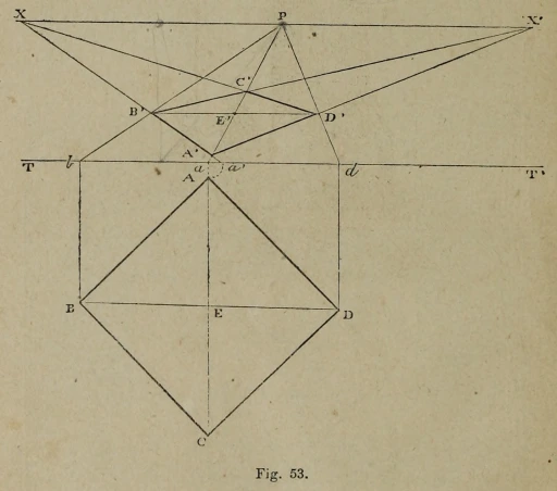
Operation: Let there be in the geometric plan the square of the angle ABCD (Fig. 53), lowered beneath the line of the plan TT’, elevate the vertical lines Bb-Aa-Dd, and conduct the receding lines bP-aP-dP; one opening of the compass equal to Aa, mark this scale in aa’ and make the receding diagonal a’X, which gives on the receding aP the intersecting point A’ and on the receding line bP the intersecting point B’: the receding side A’B’ represents the geometric AB.
Conduct the diagonal B’D’ as a horizontal line and the receding line D’X, which places on A’P the point C’, the far corner of the receding square, that we terminate by completing the sides B’C’-A’D’. The receding square A’B’C’D’ appears in perspective as the geometric square ABCD.
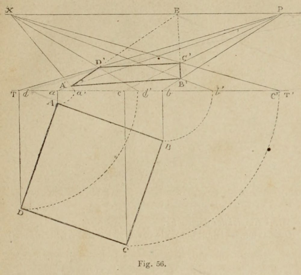
How to put a rotated square in perspective at any angle
Learning how to rotate objects in perspective is incredibly important, and if you have trouble judging rotations in 3D space by eye alone there is a solution – with this exercise you can do it without having to rely on tricks by dividing ellipses or relying on intuition which when you are a beginner can fail you.
This technique is used in modern day by architects and was used centuries ago by renaissance artists to put objects accurately into 3D space, so I think it is worth learning especially if you want to emulate that style.

The given square viewed obliquely so that its sides and its diagonals recede to the accidental points (1) which are for the most part, always out of the drawing area or inaccessible (2), it would be impossible to establish the regularity of the traced image in perspective without the help of the geometric plan.
Operation: Let the plan be lowered underneath the line of the plan in ABCD (Fig 56).
Apply successively the prior techniques to the four corners of the square which have been described (fig 42, fig 55), that is to say: elevate the vertical guides Dd-Aa-Cc-Bb; report, in drawing the arcs of the circle, the points on the ground line in a’, d’, b’, c’: construct the receding lines dP-aP-cP-bP and the receding diagonals, a’X-d’X-b’X-c’D; reunite the intersecting points A’, B’, C’, D’, by the right angle lines A’B’-B’C’-C’D’-D’A, which will form the receding oblique square A’B’C’D’, the perspective projection of the geometric square ABCD.
Summary
In this blog post I have translated several exercises from French to English, from the book Elements de Perspective by Armand Cassagne (originally published 1874) available on the Internet Archive. I think this is a highly valuable resource with the instructions clearly given, like following a mathematics or geometry textbook. If you would like to peruse more of the exercises, you are welcome to do so. I will translate more exercises for this blog in future as part of a series. In the meantime, you are welcome to view the free English book, The Theory and Practice of Perspective by G. A. Storey from the Project Gutenberg website, which has some similar exercises. However I feel this book is not as well explained or illustrated.
Next post, I will cover perspective grids or floor tiles.
If you want to jump ahead to something more complicated, I have written in another blog post about a classical architecture treatise, Perspectiva Pictorum by Andrea Pozzo.
If you want to keep up to date, feel free to follow me on Twitter, join my Mailing list, or follow the blog. Leave a comment or contact me if you have any questions!
As this is an archived post, there are no hyperlinks to a Mailing list, it's an artifact of when this was hosted on Wordpress.